■ Hitachi still seeking fixes as new cracks emerge
■ Complex structural issues
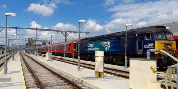
■ Class 68 locos withdrawn
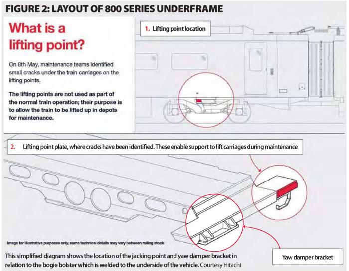
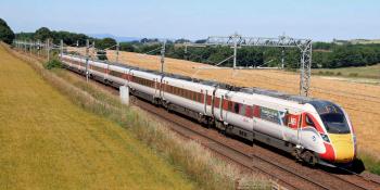
With more details of the jacking point cracks affecting the Hitachi 800 Series trains in service with Great Western, LNER, Hull Trains and TransPennine Express becoming available since the June ‘Informed Sources’ went to press, I can clarify the location of the cracks. I had assumed, wrongly, from the limited information initially available, that the cracks were in the pocket underneath the vehicle body.
When in place, the free end of the lifting bracket on the jack slides into the pocket. This provides positive location and also takes the downward reaction force when the vehicle is lifted.
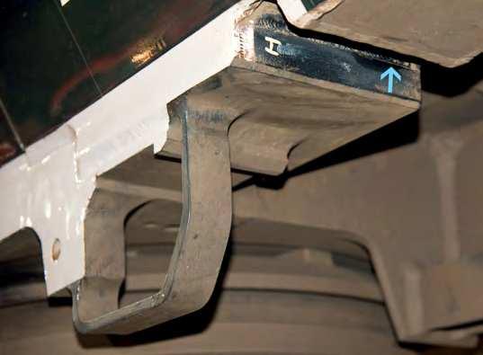
However, it subsequently emerged that the cracking occurred in the machined block of aluminium (Photo 1) which forms the lifting pad. This rests on the lifting bracket and transfers the load to the vehicle structure.
About the size of an old-fashioned telephone directory (Photo 2), this rectangular block is welded to the bolster round its four top edges (not sure whether readers are au fait with this archaic reference – Ed).
Anyway, it is along the sides of this block, just below the edges, that cracks have been detected.
CONSTRUCTION
As explained last month, aluminium bodyshells are produced by welding together long aluminium extrusions. These extrusions are created by using giant presses to squeeze aluminium through dies under high pressure. Readers with children may remember the Play-Doh extrusion press, which works on the same principle.
Aluminium extrusions for vehicle bodies are double-sided, with internal stiffening webs.
They are not strong enough to take the loads associated with bogie pivot forces. This is the job of the load-bearing bolster which is welded to the extrusions underneath the vehicle and is also fabricated from aluminium.
With the 800 Series, the lifting block is welded to the bolster, which is then welded to the underside of the bodyshell. Figure 2 is a simplified diagram of the Class 800 bolster which also includes the yaw damper bracket.
MYSERY CRACKS
So why is what is essentially a block of aluminium welded to a bolster and which takes only a quarter of the weight of the vehicle, and then only when it is lifted in the depot, cracking? And cracking to the extent that there is sufficient concern that it might come adrift in service for trains to be grounded?
After the first cracks had been found, Hitachi revisited the Finite Element Analysis of the bolster area, which confirmed the lifting block was stressed only when the train was being lifted. That it had no effect on the structural integrity of the vehicle itself was a factor in allowing trains to return to service with cracking being monitored.
Early on, Hitachi identified the cause of the cracking as stress corrosion which, according to the company, depends on the conjunction of three conditions. These are: the material, a manufacturing issue and the environment. This ‘triangle’ was present in the case of the lifting block.
ALUMINIUM GRADE
Note the reference to material. Where the European train manufacturers such as Siemens and Alstom/Bombardier use 6000 Grade aluminium alloy for their bodyshell extrusions, Hitachi employs 7000 Grade.
This is the strongest/hardest of the aluminium alloys, but is more demanding to weld and more prone to stress corrosion. While Hitachi’s long-standing expertise in friction stir welding avoids the first problem, the rapid identification of stress corrosion in the case of the lifting point may be significant.
Having identified the cause of the lifting point cracking, Hitachi is developing the solution, with verification support by The Welding Institute and Ricardo Rail. Reading between the lines, it looks as though the lifting point problem is understood and the current work is to identify the most effective repair.

STRUCTURE
That said, I don’t entirely buy the argument that the lifting pad is not a structural issue. When it is used it is under compression and my understanding is that you require tensile stress for fatigue cracking.
Second, while it is not structural, it is welded to the vehicle structure and is thus subject to forces in and around the bolster area. And these are likely to be complex, not least because of the overhang outboard of the bogie centres. This is the result of a 26-metre-long vehicle restricted to 17 metres between bogie centres.
At the non-cab end of a Class 800 Driving Pantograph Transformer (DPT) vehicle, the water and effluent tanks for the Controlled Emission Toilet (CET) are at the extreme vehicle end.
This means upwards of three-quarters of a tonne of liquid is subject to dynamic forces when the train is on the move. And the maximum bending force will be close to the location of the jacking pad.
This, itself, is below the passenger door, where the cut-out reduces the local stiffness of the bodyshell.
YAW DAMPER
Meanwhile, the yaw damper bracket cracking remains a work in progress. An 800 Series train with a bogie and bolster fitted with strain gauges was running at the end of May.
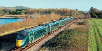
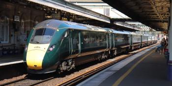
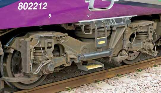
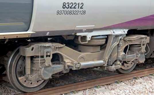
Complicating the issue is the variety of bogie configurations on the 800 Series trains. First, the intermediate vehicles have a raised floor compared with the Driving Pantograph Transformer cars (DPT). This means a longer yaw damper arm, which can be compared in Photos 3 and 4. Adding to the variety is the inside frame bogie fitted to the trailer vehicles in nine-car formations.
Then, to control pantograph sway, DPT vehicles are likely to have stiffer anti-roll bars. The connection of the anti-roll bar link to the yaw damper bracket varies. On the motored cars, the anti-roll bar link is connected to the yaw damper arm, while on the DPT it bolts directly to the yaw damper bracket.
In the case of the yaw damper bracket cracking, a further consideration, noted by Hitachi informed sources, is that the 26-metre vehicle length, encouraged by the Department for Transport specification, means the bodyshell had to be narrower than the Class 395.
3.15 RIDE
TS425: The ride comfort of the IEP Vehicles shall be assessed in accordance with DD ENV 12299:1999 ‘Railway Applications – Ride Comfort for Passengers – Measurement and Evaluation’.
For each measuring location (which may be at any point along the saloon) within the saloon, the arithmetic mean of all Ride Indices (as defined in DD ENV 12299:1999 ‘Railway Applications – Ride Comfort for Passengers – Measurement and Evaluation’ taken at that point when operating at maximum linespeed in both the Tare Condition and the Fully Seated Condition must be:
■ Less than 1.6 when measured on the East Coast main line over track with characteristics equivalent to those defined by the East Coast main line Track Data;
■ Less than 1.9 when a simulation is performed, using a dynamic model of the train validated through testing on the East Coast main line, of an IEP Unit on track with characteristics as defined by the Midland main line Track Data.
IEP Train Technical Specification
This, in turn, meant Hitachi’s original bogie configuration for the UK market had to be redesigned. Despite initial ride issues, the Class 395 has not suffered from yaw damper bracket issues, even though it is manufactured with the same material.
TRACK QUALITY SUSPECT?
There have been suggestions that the yaw damper cracking could be linked to track quality. Pre-lockdown personal experience of the Class 800 showed the lateral ride to be poor between Paddington and Reading based on the standard Ford £1 coin balancing ride meter.
Since the accelerations felt within the vehicle have been, theoretically, attenuated by the yaw damper, the transfer of forces between the bogie and the attachment of the yaw damper arm will reflect ride quality.
Ride quality is measured by averaging the votes of test passengers using a scale from 0 (perfect) to 5 (poor). There are, of course, lots of clever formulae using measured accelerations from instrumented vehicles. And I have my £1 coin.
But ride is essentially subjective, hence the vote averaging system.
UK TRACK
Bidders for IEP were given two sets of files containing track geometry data in VAMPIRE® format. As the memorable acronym suggests, VAMPIRE was a product of British Rail Research.
Intended for evaluation of ride comfort using computer simulations, each file contained a 500-metre run-in, followed by exactly five minutes of measured track data from the specified route when running at linespeed.
For the ECML, the sections of route were Retford – Newark, Stoke – Peterborough and Huntingdon – Welwyn. For the MML, the sections were Luton – Ampthill, Ampthill – Wellingborough and Kettering – Market Harborough. But note these were provided for ride purposes and suspension characteristics, not structural design.
Indeed, according to informed sources, when whoever was running Inter-city East Coast at the time complained about the ride when the first Azumas started running, the response was that it met the specification.
ROUGH
Now it is true that track quality on the Great Western main line is not the billiard table it was in the days of legendary Chief Civil Engineer Philip Rees. But, subjectively, it is not significantly worse than the Midland main line – and note that the Train Technical Specification allowed a poorer ride index when the MML data was used for simulation.
CLASS 68
Class 68 locomotives were withdrawn in May when cracks were found in the steel brackets supporting the underframe mounted head end power modules. In old-railway-speak, Electric
Train Heating (ETH) supply. According to informed sources, metallurgical inspection showed these to be a classic case of metal fatigue in steel. A redesign should do the trick.